MAX7219 Dot matrix module MCU control Display module DIY kit for Arduino
Preis 19.66 USD
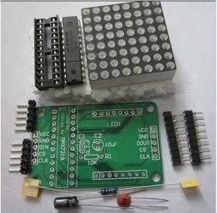
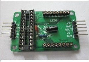
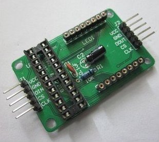
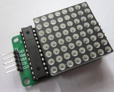
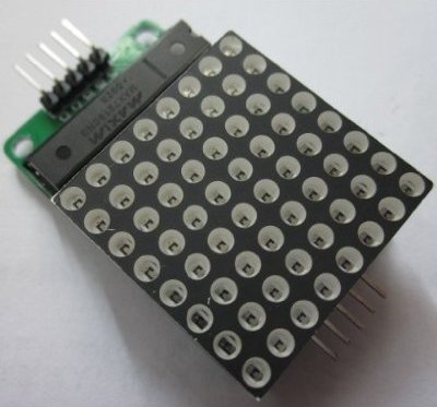
Wiring instructions: 1.The module left as an input port to the output port on the right. 2.The control of a single module, simply input port to the CPU 3.Multiple modules cascade input termination CPU, 2 output termination module, a module of the input of the input terminal, the output terminal of the first two modules of the first three modules, and so on ... 51 MCU, for example: VCC ? 5V GND ? GND DIN ? P22 CS ? P21 CLK ? P20 Package: DIY kits 1x PCB board 2x 5P bent pin single row pin 1x 24P IC socket The 1x Inline MAX7219 chip 1x 10uF electrolytic capacitor 1x 0.1uF ceramic capacitor 1x 10K resistor 2 Block 2x 8P round hole (pitch 2.54mm) 1x 3mm 8 * 8 common cathode red dot Note: 1.VCC and GND is not reversed, it would burn the chip! 2.When the 51 microcontroller P0 port control, must be connected to the pull-up resistor, it is recommended that the resistance of 4.7K--10K. 3.Please lattice into the hole first seat, and then inserted into the round hole Block PCB board welding. Lattice word side facing the surface order from left to right pin 123456. PCB board 1 foot square pad! 4.Electrolytic capacitors long-legged as positive, negative short legs; ceramic capacitor without the positive and negative points.